Pixhawk Mini Wiring Quick Start
This quick start guide shows how power the Pixhawk Mini and connect its most important peripherals.
Under construction.
Standard Wiring Chart
The image below shows standard quadcopter wiring using the Pixhawk Mini Kit and 3DR Telemetry Radios (along with ESC, motor, battery and a ground control station running on a phone). We'll go through each main part in the following sections.
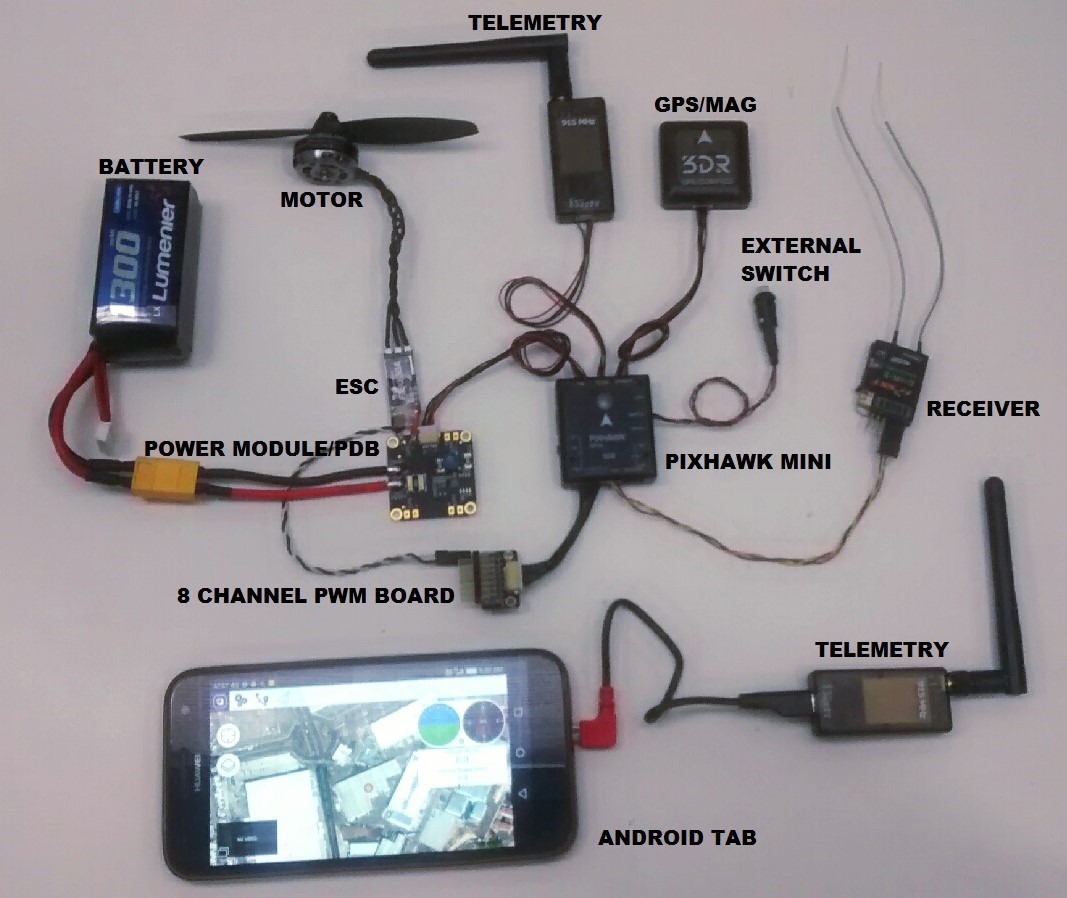
The output wiring/powering is slightly different for other types of vehicles. This is covered in more detail below for VTOL, Plane, Copter.
Mount and Orient Controller
The Pixhawk Mini should be mounted on the frame using vibration-damping foam pads (included in the kit). It should be positioned as close to your vehicle’s center of gravity as possible, oriented top-side up with the arrow points towards the front of the vehicle.
![]()
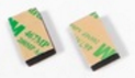
If the controller cannot be mounted in the recommended/default orientation (e.g. due to space constraints) you will need to configure the autopilot software with the orientation that you actually used: Flight Controller Orientation.
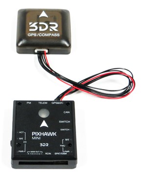
GPS + Compass
Attach the 3DR GPS + Compass to the Pixhawk Mini's GPS&I2C port (top right) using the supplied 6 pin cable. The GPS/Compass should be mounted on the frame as far away from other electronics as possible, facing the front of the vehicle (separating the compass from other electronics will reduce interference).
NOTE - INSERT IMAGE SHOWING BOTH PORTS? OR FRONT-FACING image of GPS&I2C
[IN CALIBRATION, IS ORIENTATION TO VEHICLE FRONT or RELATIVE TO PIXHAWK?]
The compass must be calibrated before it is first used. For more information see: [COMPASS CALIBRATION LINK]
Power
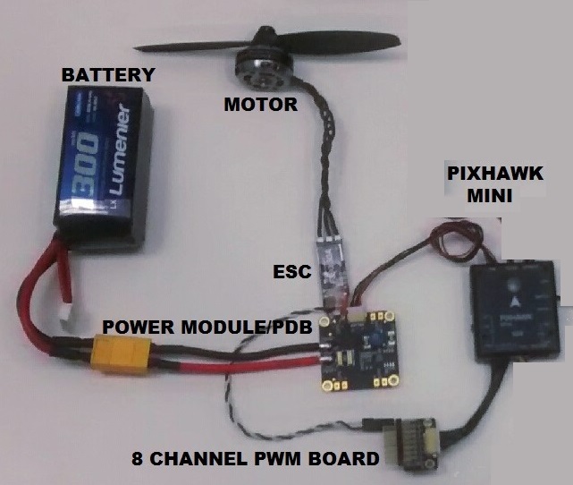
The image below shows typical power-supply wiring when using Pixhawk Mini in a Quadcopter. This uses the Quad Power Distribution Board that comes in the kit to supply both the Pixhawk Mini and the ESC/Motor from the battery (and can also power other accessories).
The Quad Power Distribution Board includes a power module (PM) that is suitable for batteries <= 4S. The 3DR 10S Power Module is recommended if you need more power.
[PLACHOLDER IMAGE - need more detail and consistent name for power board]
The Pixhawk Mini is powered through the PM port. When using a power module (as in this case) the port will also read analog voltage and current measurements.
Up to 4 ESCs can be separately powered from the power distribution board (though in this case we only have one connected).
The control signals come from MAIN OUT. In this case there is only one control channel, which is connected to the ESC via the 8 Channel PWM Breakout Board.
The Pixhawk Mini output rail (MAIN OUT) cannot power attached devices (and does not need to in the circuit as shown). For vehicles where MAIN OUT is attached to devices that draw power (e.g. a servo used in a plane) then you will need to power the rail using a BEC (battery elimination circuit). The included breakout board allows one channel to provide power on the other outputs. [Show a diagram of this?]
Radio/Remote Control
Pixhawk Mini supports many different radio receiver models:
Spektrum and DSM receivers connect to the SPKT/DSM input.

PPM-SUM and S.BUS receivers connect to the RCIN port.

PPM and PWM receivers that have an individual wire for each channel must connect to the RCIN port via a PPM encoder like this one (PPM-Sum receivers use a single signal wire for all channels).
For more information about selecting a radio system, receiver compatibility, and binding your transmitter/receiver pair, see: Remote Control Transmitters & Receivers.
Safety switch (optional)
The controller has an integrated safety switch that you can use for motor activation once the autopilot is ready to take off. If this switch is hard to access on a particular vehicle you can attach the (optional) external safety button, as shown below.
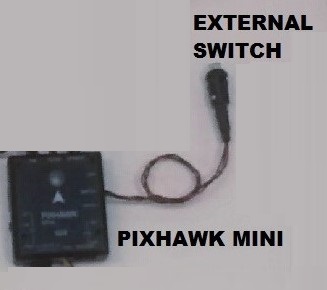
[IMAGE PLACEHOLDER - GOOD IMAGE of SIDE PORTS + CONNECTED SWITCH]
Telemetry Radios
Motors
The mappings between MAIN/AUX output ports and motor/servos for all supported air and ground frames are listed in the Airframe Reference.
The mapping is not consistent across frames (e.g. you can't rely on the throttle being on the same output for all plane frames). Make sure to use the correct mapping for your vehicle.
If your frame is not listed in the reference then use a "generic" airframe of the correct type.
Notes:
- The output rail must be separately powered, as discussed in the Power section above.
- Pixhawk Mini cannot be used for QuadPlane VTOL airframes. This is because QuadPlane requires 9 outputs (4 Main, 5 AUX) and the Pixhawk Mini only has 8 outputs (8 Main).

Other Peripherals
The wiring and configuration of other components is covered within the topics for individual peripherals.
Configuration
General configuration information is covered in: Autopilot Configuration.
QuadPlane specific configuration is covered here: QuadPlane VTOL Configuration