Racer Setup
This page describes how to setup a racer and get the best performance out of it, particularly in acro mode.
Many things described here can also be applied to other multicopters to improve flight performance.
Keep in mind that racers are fast vehicles, specifically designed to be overpowered, and thus you should already have some experience, or let someone with experience help you.
A racer usually leaves away certain sensors, such as the GPS, which means that less failsafe options are available.
Build Options
Racers typically do not have a GPS, but you will get some benefits if you add one.
Minimal
PX4 can go as minimal as using only a gyro and an accel sensor. If the board has an internal mag, it should not be used as it typically suffers from strong interferences (this is especially true for a small racer).
GPS with external Mag
A GPS adds some weight and it should be placed away from high currents to avoid mag interferences (on a GPS mast), which unfortunately means it will easily break during crashes. On the other hand you get some benefits, that are interesting especially for beginners:
- You can go into position hold and the vehicle will just stay in one place. This is handy if you lose the orientation or need a brake. It can also be used to land safely.
- Return mode can be used, either on a switch or as RC loss/low battery failsafe.
- You will have the last position when it crashes.
- The log contains the flight track, which means you can review the flight (in 3D). This can help to improve your acro flight skills.
During agressive acro maneuvers the GPS can lose its position fix for a short time. If you switch into position mode during that time, altitude mode will be used instead until the position becomes valid again.
Vehicle Setup
The following paragraphs describe a few important points when building the vehicle. If you need complete build instructions, you can follow the QAV-R 5" KISS ESC Racer build log.
Vibration Setup
There are various ways how to do the mounting to reduce vibrations, and there is probably not a single best method. You will however have much less problems with vibrations if you use high-quality components (frame, motors, props) as for example used in this build. Make sure to use balanced props. The FC can be mounted with O-rings.
Center of Gravity
Make sure that the center of gravity is as close as possible to the center of thrust. Left-right balance is usually not a problem, but front-back. You can move the battery until it is correct and mark it on the frame so you will always place it correctly.
The integral term can account for an imbalanced setup, and a custom mixer can do that even better, but it's best to fix it in the vehicle setup.
Software Setup
After having built the racer, you will need to configure the software. Go through the Basic Configuration Guide and choose the Generic 250 Racer airframe, which already sets some racer-specific parameters. These parameters are important:
- Enable One-Shot by setting
PWM_RATEto 0. - Enable
SYS_FMU_TASK(explained below). - Set the maximum roll-, pitch- and yaw rates for Manual/Stabilized mode as
desired:
MC_ROLLRATE_MAX,MC_PITCHRATE_MAXandMC_YAWRATE_MAX. The maximum tilt angle is configured withMPC_MAN_TILT_MAX. - The minimum thrust
MPC_MANTHR_MINshould be set to 0. - Disable RC input filtering by setting
RC_FLT_CUTOFFto 0.
Estimator
If you use a GPS you can skip this section and use the default estimator.
Otherwise you should switch to the Q attitude estimator, which works without mag
or baro. To select it, set SYS_MC_EST_GROUP to 1, and change the
following parameters:
- Set
SYS_HAS_MAGto 0 if the system does not have a mag. - Set
SYS_HAS_BAROto 0 if the system does not have a baro. - Configure the Q estimator: set
ATT_ACC_COMPto 0,ATT_W_ACCto 0.4 andATT_W_GYRO_BIASto 0. You can tune these later if you wish.
Failsafe
Configure RC loss and low battery failsafe. If you do not use a GPS, set the failsafe to Lockdown, which turns off the motors. Test RC loss on the bench without props attached by turning off the remote when the vehicle is armed.
Make sure to assign a kill switch, test it and train to use it (or use an arm switch).
Arm switch
To use an arm switch manually set the parameter RC_MAP_ARM_SW to the
corresponding switch RC channel. The vehicle should from then on immediately
arm/disarm whenever your switch is tuned on/off. If the switch positions are
reversed just change the sign of the parameter RC_ARMSWITCH_TH or also change
its value to alter the threshold value. Make sure to test this under safe
conditions!
PID tuning
At this point you should be ready for a first test flight.
If it goes well, do a first pass of PID tuning (ignore the thrust curve settings). The vehicle needs to be undertuned, meaning the P and D gains should rather be set too low so that there are no oscillations from the controller that could be interpreted as noise (the default gains might be good enough). This is important for the filter tuning. There will be a second PID tuning round later.
Make sure to calibrate the ESCs before doing any tuning.
Control Latency
The Control Latency is the delay from a physical disturbance of the vehicle until the motors react to the change. It is crucial to reduce the control latency as much as possible: a lower latency allows to increase the rate P gains, which means better flight performance. Even 1 millisecond (!) added to the latency makes a difference. These are the factors that contribute to the latency:
- A soft airframe or soft vibration mounting (they act as a filter).
- Low-pass filters in software and on the sensor chip.
- PX4 software internals: the sensor signals need to be read in the driver
and then pass through the controller to the output driver.
Enable
SYS_FMU_TASKto reduce latency (default on Pixracer and Omnibus). - The IO chip (MAIN pins) adds about 5.4 ms latency compared to using the AUX pins.
This does not apply to a Pixracer or Omnibus F4, but for example to a Pixhawk.
To avoid the IO, disable
SYS_USE_IOand attach the motors to the AUX pins instead. - PWM output signal: enable One-Shot (
PWM_RATE=0) to reduce latency.
Filters
As mentioned in the previous section, filters affect the control latency. This is the filtering pipeline for the controllers in PX4:
- On-chip DLPF for the gyro sensor. The cutoff frequency is set to 98Hz and it is sampled with 1kHz.
- Low-pass filter on the gyro sensor data. It can be configured with the
IMU_GYRO_CUTOFFparameter. - Low-pass filter on the D-term. The D-term is most suspectible to noise while
slightly increased latency does not negatively affect performance. For this
reason the D-term has an additional low-pass filter, configurable via
MC_DTERM_CUTOFF. - A slewrate filter on the motor outputs (
MOT_SLEW_MAX). Generally not used.
To reduce the control latency, we want to increase the cutoff frequency for the low-pass filters. However this is a trade-off as it will also increase the noise of the signal, which is fed to the motors. Noise on the motors has the following consequences:
- Motors and ESCs can get hot, to the point where they get damaged.
- Reduced flight time because the motors continously change their speed.
- Visible random small twitches.
The best filter settings depend on the vehicle, and the defaults are set conservative such that it works on lower-quality setups as well.
Filter Tuning
First make sure to have the high-rate logging profile activated
(SDLOG_PROFILE parameter). Flight Review will then show an FFT plot for the
roll, pitch and yaw controls.
Do not try to fix a vehicle that suffers from high vibrations with filter tuning. Rather fix the vehicle first.
Filter tuning is best done by doing a flight and then looking at the log. You can do multiple flights right after each other with different parameters and then inspect all logs, but make sure to disarm in between so that separate log files are created.
The performed flight maneuver can simply be hovering in stabilized mode with some rolling and pitching to all directions and some increased throttle periods. The total duration does not need to be more than 30 seconds. In order to better compare, the maneuver should be similar in all tests.
First tune the gyro filter IMU_GYRO_CUTOFF by increasing it in steps of 10 Hz
while using a low D-term filter value (MC_DTERM_CUTOFF = 30). Upload the logs
to https://logs.px4.io and compare the Actuator Controls FFT plot. Set the
cutoff frequency to a value before the noise starts to increase noticeably (for
frequencies around and above 60 Hz).
Next tune the D-term filter (MC_DTERM_CUTOFF) in the same way.
Below is an example for three different filter values. At 90 Hz the general noise
level starts to increase (especially for roll), and thus a cutoff frequency of 70
Hz is a safe setting.
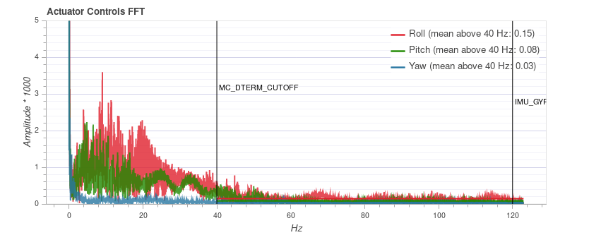
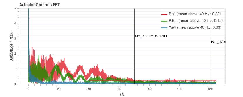
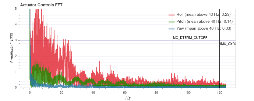
The plot cannot be compared between different vehicles, as the y axis scale can be different. On the same vehicle it is consistent and independent of the flight duration though.
PID tuning
Now do a second round of PID tuning, this time as tight as possible, and also tune the thrust curve.
Airmode
After you verified that the vehicle flies well at low and high throttle, you can
enable airmode with the MC_AIRMODE parameter. It makes sure that the
vehicle is still controllable and tracks the rate at low throttle.
Happy flipping :)